Here's a TOC:
Electrical
I'll draw heavily on Wikipedia in this post. Here's a diagram of a feedback amplifier:
Engineers think of how this circuit would operate on sinusoids, so the open loop gain AOL and the feedback factor β may be frequency dependent. The formula for closed loop gain is:

If β is positive, in this convention, the feedback is negative, because it is fed back to the negative input port. And the closed loop gain is less than open-loop. But note that the statement that it is negative is frequency dependent.
The closed loop gain is the factor by which you multiply a frequency component of the input I(f) to get the output O(f).\[O(f)=A_{fb}(f) I(f)\] And if you go to the time domain by inverse Fourier Transform, this becomes a convolution: \[O(t)=\int_{-\infty}^{t}\hat{A}(t-\tau)I(\tau) d\tau\] where \(\hat{A}\) is the inverse Fourier Transform of the closed loop gain Afb
Factor: For consistency, set α = -β. Then the ranges are:
- α < 0 : negative feedback - stable
- 0 < α < 1/AOL : positive feedback - stable (but getting less so)
- α > 1/AOL : positive feedback - unstable (oscillation)
Z-transform
EE's often use a Z-transform to represent time series in a kinda frequency domain way. I think of it as a modified discrete-time Fourier transform. It renders the transfer function as, often, a rational function and allows you to study the stability and other aspects of the response in terms of the location of its poles. More laterTime Series
Feedback is the AR part of ARMA. The transfer function is analogous to a version with exogenous inputs (ARMAX). Or you can look at the original version as formally analogous with the noise acting as input.Anyway, if you treat the lag operator as a symbolic variable, you see again a rational function acting as a transfer function. That is developed into a Z-transform equivalence here.
Factor: In time series, there isn't a commonly used equivalent of the boundary between positive and negative feedback, in the amplifier sense. There is a stability criterion, which can be got from the Z-transform expression. It requires locating the roots of the denominator polynomial (poles). Then, in this formulation, the roots have to have magnitude >1 for stability. For 1st order:
\[y_n+a_1 y_{n-1}=...\]
the requirement is that |a1| < 1.
Climate - equilibrium
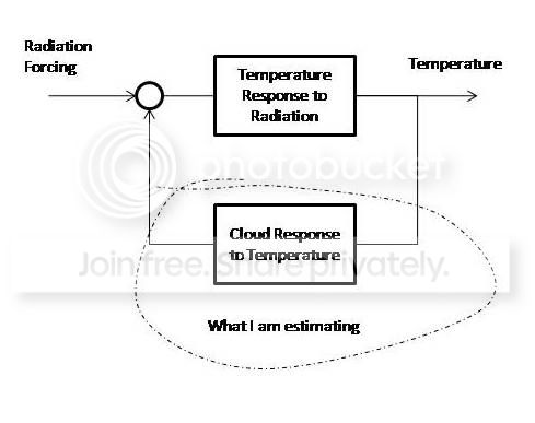
This goes back at least to the Cess definition used by Zhang et al 94, for example. Suppose you have equilibrium T=0 and flux=0. Then you impose a forcing G W/m2. The system incorporates a number of temperature dependent flux terms Fi, which, with the sign convention of G, each vary with T asΔFi = -λi ΔT.
So the new equilibrium temperature is
T = G/λ,
where λ is the sum of the λi. The nett feedback is negative, else runaway, but the components of the sum could be positive or negative.
Globally, for example, there is a base "no-feedback sensitivity" feedback of about 3.3 W/m2/C, based just on BB radiation. The exact amount is not important here. That gives the often quoted 1.2 C per CO2 doubling. Although not usually thought of as a feedback, it goes into the sum of feedback factors. The λi that add to it are called negative feedbacks, because they add to the stabilization. Those that subtract are positive.
Comparison with Elec and Time Series - much simpler.It's equilibrium (DC) - there are no dynamics. Time does not appear.
Climate - non-equilibrium
DS11 and SB11 add some thermal dynamics, with the equation \[C dT/dt = G - \lambda T\] measuring the time response to the perturbation provided by G. Their time scales are too short to assume equilibrium. This approaches steady state as the temperature approaches G/λ, the sensitivity value. C is the thermal capacity. Adding the gross dynamics does not change the feedback concepts (though it expresses the potential for thermal runaway). In EE terms, C is a single capacitance,and you could think of it as a resistance (1/λ)-capacitance(C) circuit. But I don't think that changes any of our feedback issues.
[Added:]
The DE shows an ARMA analogue if you convert the derivative to a difference:
\[T_n-T_{n-1} = -\lambda {\delta}t T_n + {\delta}t F(t_n) \] or
\[T_n = (T_{n-1}+ {\delta}t F(t_n))/(1+\lambda {\delta}t) T_n \]
which starts to look like the closed loop gain equation. But it's also very like ARMAX(1,0,1)
The differential equation has the solution:
\[O(t)=\int_{-\infty}^{t}e^{\lambda*(t-\tau)}F(\tau) d\tau\]
very like the iFT time domain expression of the closed loop gain. It has, however, a restricted transfer function, corresponding in EE terms to a single pole. This can be seen by Laplace Transform:
\[s \hat{T} - T(0)=-\lambda \hat{T} +\hat{F}\]
or \[\hat{T}= (T(0) + \hat{F})/(s +\lambda)\]
There are plenty of ways to generalise the de approach. T could be a vector and λ a square matrix, which would give multiple poles. Or λ could be a function of t, perhaps with a convolution operation.
Comparison with Elec and Time Series - simple dynamics of heat storage. But there are no time-scales associated with the individual feedbacks. They are not reactive. I don't think there is any need to consider phase shift in the feedback.


