But I have come back to thinking about plane projections. One reason is that I post images on Twitter, where I can't use Javascript. Another is that I compare TempLS output with GISS and other indices, and often their default presentation is with some other projection. So I have looked at schemes such as Mollweide and Robinson, the latter being used by GISS and others.
This has linked in with another aspect of what I do, which is using Platonic solids as a basis for gridding for integration of temperature, and perhaps for graphics. As a by-product, I showed some equal area projections based on the cubed sphere. I have recently been using icosahedral grids in the same way, and that yields equal area maps with even less distortion, but which are also particularly informative for these applications.
So in this post I want to touch on some of these points. First the conventional projections.
Mollweide and Robinson
These are of course well-established. But I found the Wiki versions of the implementation unnecessarily hard to implement, so I'll describe in an appendix some simple approximating formulae. The Mollweide projection achieves equal area at a cost of some distortion near poles. Equal area can be desirable, as for example in not exaggerating the weather variations near poles. One particular use I will describe is in displaying the extent of coverage of temperature stations. Here is a typical map: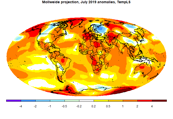
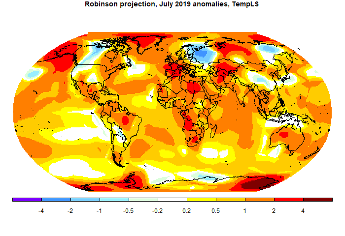
I am not a fan of the Robinson projection. It is billed as a compromise, but I think it is thus neither fish nor fowl. It is not much closer to equal area than lat/lon, and it does little to reduce distortion. It seems to be popular because it seems not unfamiliar to people used to equirectangular. However, it should be easy to implement, so there is little to lose by using it. I say should be, but in fact they make a considerable rigmarole, presenting a table of numbers to be used, and even fussing about how to interpolate. This may be because there are still ownership issues, although there seem to be no restrictions on use. Anyway, I'll describe my way of implementing in the appendix.
Icosahedral projection
I'm developing yet another method of integration, based on FEM on an icosahedral mesh. I'll post soon. But meanwhile it makes for an interesting projection.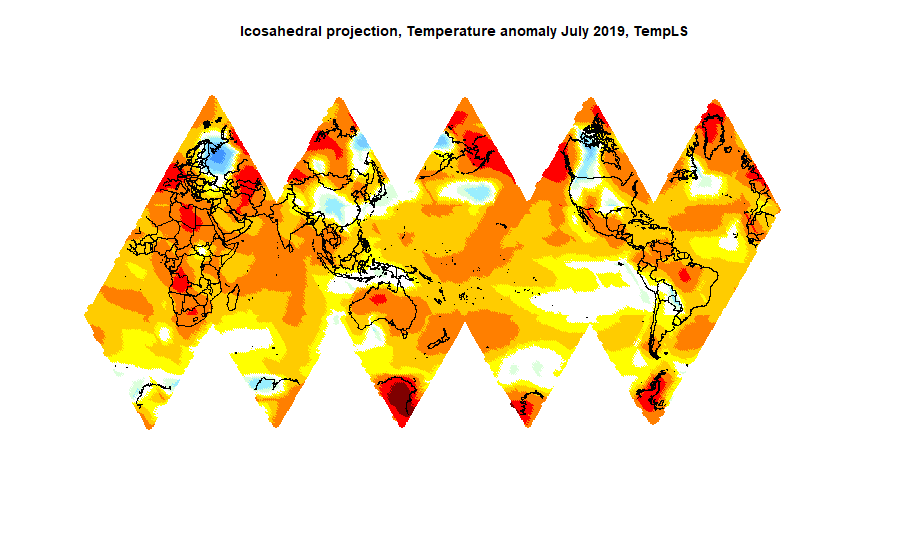
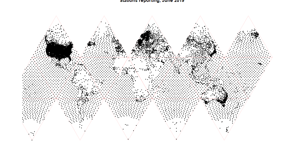
It is very close to equal area. This is achieved at the expense of more numerous cuts. It is not so easy to figure out, and may not be the best projection for this purpose. But it is more useful for showing the distribution of stations, where area density is more critical. I'm using it to see reasons for possible failure of an integration scheme based on icosahedra. Here is the plot:
What next?
I'll try using the Robinson projection for the regular TempLS reports, mainly to make it easier to compare with others. I'll probably also occasionally show a Mollweide projection.Appendix - calculation methods
As I mentioned, I found the Wiki versions surprisingly clunky, so I spent some time developing simpler ways. I need that partly because I have to be able to reverse. When I show a color plot, I need to define a grid of points on the projection, map back to the sphere for interpolation, and then bring the colors back.Both the Mollweide and Robinson projections have a similar simple basis. There is one mapping of latitudes from old to new, and then a formula for scaling the longitudes. Latitudes remain as horizontal lines. So two functions of a single variable (each) need to be approximated. There is a little difficulty with singularity in the Mollweide.
In each case, the latitude transform is an odd function (about zero latitude), and the longitude scale is even. I require the approximation to be exact at the equator and poles, and a least squares fit elsewhere. So generally, if the original coordinates are (x,y), x=longitude, angles in right angle units, and the projection coords are (X,Y), the mapping is
Y=f(y)=y+y(1-y²)(a₀ +a₁y² +a₂y4 +...)
X=x*g(y); g(y)=1-d*y²+y²(1-y²)(b₀ +b₁y² +b₂y4 +...)
The inverses are
y=F(Y)=Y+Y(1-Y²)(c₀ +c₁Y² +c₂Y4 +...)
x=X/g(y)
For the Robinson projection I find the coefficients by fitting to the data tabulated by Wiki. d is just what is needed to get X right at y=1, so = 1-X there. From the table, that is d = 1-0.5322 = 0.4678.
The coefficients are, to four terms:
| a: | 0.1123 | 0.1890 | -0.1722 | 0.2326 |
| b: | -0.0885 | -0.3568 | 0.8331 | -1.0023 |
| c: | 0.1782 | -0.6687 | 1.1220 | -0.8133 |
The Mollweide formula relates f(y) in terms of an intermediate variable a :
Y=sin(a)
2a+sin(2a)=π sin(π/2 y)}}
So I generate a sequence of values of a between 0 and π/2, and hence y and Y sequences that I can use for fitting, to get f and F. But first there is a wrinkle near y=1; the expansion of the second equation there relates (1-a)³ on the left to (1-y)², and it is necessary to take fractional powers. The simplest thing to do is to first transform
z=sqrt(1-(1-y²)^(4/3))
and then do the expansion in z. Then it is necessary to map back again
Y=sqrt(1-(1-z²)^(3/4))
However, a simplification is now that the function g(y) is just sqrt(1-y²). And d=1. So the series are:
a:(0.06818,0.01282,-0.01077,0.01949)
c: (-0.06395,-0.0142,0.00135,-0.0085)
All these approximations give considerably better than three sig fig accuracy, which means error much less than a pixel.
Many thanks for posting this. I first tried a simple power series but of course the ends did not match perfectly. Your approach to anchoring the ends is a master stroke. My a coefficients match yours; my c match your b; and my b match your c except my b0 = 0.1782 (compare to your c0 = 0.782 -- curious missing 1!).
ReplyDeleteThanks. I'll check the b0; looks like I mis-typed
DeleteYes, a mistype. Here is my code fragment:
Deletec=list(r=c(1,0.5322),b=c(0.1782,-0.6687,1.1220,-0.8133)),
a=list(r=0:1,b=c(0.1123,0.1890,-0.1722,0.2326)),
b=list(r=0:1,b=c(-0.0885,-0.3568,0.8331,-1.0023))